Typically we don’t discover that the battery has drained out and consequently the related gear doesn’t work correctly. By connecting this straightforward 24V/12V battery voltage stage indicator circuit throughout the battery, you may verify its voltage stage any time.
The circuit can be utilized to verify 24V and 12V batteries each. The battery stage is indicated by the ten LEDs. Every glowing LED signifies 10% of battery voltage stage. So, when LED1 via LED5 are glowing, or simply LED5 is glowing, it means the battery is round 50% charged. The circuit may help in checking the batteries for a automotive, inverter, photo voltaic system, and many others.
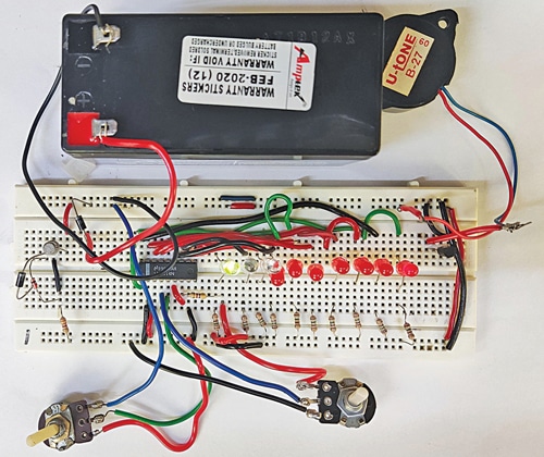
The creator’s circuit rigged on a breadboard is proven in Fig. 1 whereas the circuit’s block diagram is proven in Fig. 2.
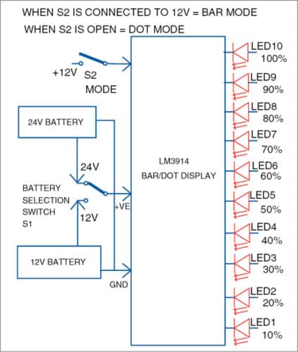
As proven within the block diagram, when LED1 alone glows it means the battery stage is barely 10%. With LED2 additionally glowing it means the battery stage is 20%, and so forth. When all of the LEDs (LED1 via LED10) are glowing, it means the battery stage is 100% and it’s match to be used.
Change S1 is used to observe both 24V or 12V battery. Change S2 helps choose dot mode or bar mode show. In dot mode solely the final LED representing the voltage glows whereas in bar made all of the LEDs as much as that LED glow. The selection is yours.
Circuit and Working
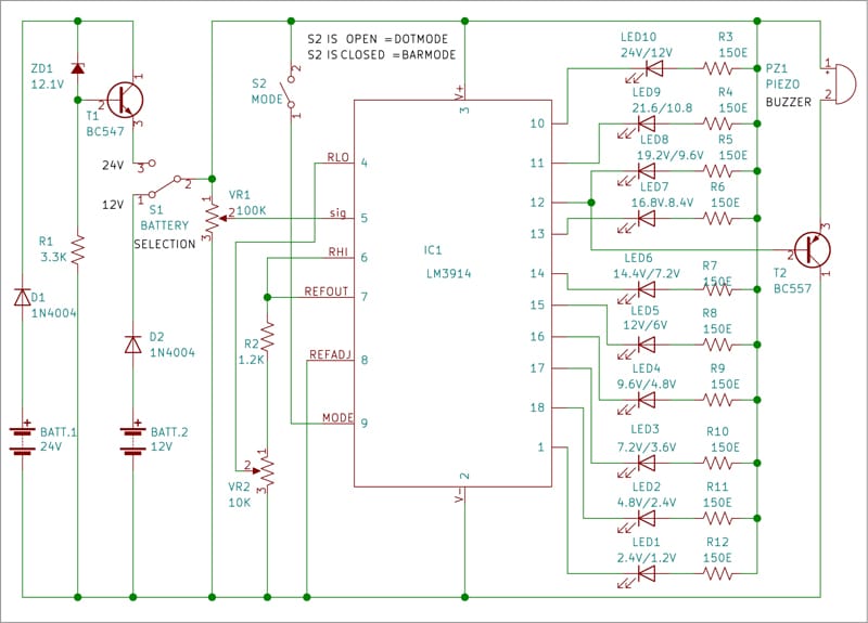
Circuit diagram of the battery voltage stage indicator is proven in Fig. 3. It’s constructed round IC LM3914 dot/bar driver IC1, 1N4007 diodes D1 and D2, ten 5mm LEDs (LED1 via LED10), 12.1V Zener diode (ZD1), BC547 transistor T1, BC557 transistor T2, presets VR1 and VR2, and piezo buzzer PZ1.
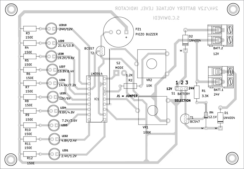
Obtain PCB and Part Structure PDFs: click on right here
The LED show comprising LED1 via LED10 exhibits voltage stage of the 24V or 12V battery chosen. This show will be set in dot mode or bar mode. For displaying the voltage stage in bar mode, join pin 9 of the IC to optimistic terminal of the battery utilizing swap S2. For displaying the voltage stage in dot mode, merely open swap S2.
The 12.1V Zener diode ZD1 is used together with BC547 transistor T1 to cut back the 24V battery voltage to 12V. Pin 3 of IC1 is related to optimistic facet of 12V to function the circuit whereas its pin 2 is related to floor.
To verify voltage stage of the battery, use two crocodile clips with about 30cm lengthy wires soldered to every. One of many clips could possibly be crimson with crimson wire soldered to it and the opposite black with black wire soldered to it. Join crimson clip to optimistic terminal of the battery below check and black clip to its detrimental terminal. Flip swap S1 for checking a 24V battery’s standing. Place of swap S2 will rely upon whether or not you need a dot show or a bar show.
Use presets VR1 and VR2 to calibrate the circuit. And you could use a 30V variable energy provide as an alternative of the 24V battery for calibration. Join 12V from the variable energy provide instead of 24V battery within the circuit. Alter preset VR1 such that LED1 simply begins glowing. Now enhance the enter DC voltage slowly to 24V and observe the LED’s glowing standing. The primary LED (LED1) will begin glowing at 2.4V and the second (LED2) at 4.8V, and so forth. The final LED (LED10) will glow at 24V.
After this calibration the circuit is able to use. If you wish to verify the extent of a 24V battery, join it to the circuit utilizing the crocodile clips and flip swap S1 in the direction of 24V place.
To see the voltage stage in dot mode, hold swap S2 open. If, say, LED9 glows, it means voltage stage of the battery is round 90% of 24V, that’s, round 21.6V. If LED10 glows, it means the battery is totally charged.
To see the battery voltage stage in bar mode, flip swap S1 in the direction of 24V place and switch swap S2 on. If, say, LED1 via LED9 begin glowing, it means voltage stage of the battery is round 90% of 24V, that’s, round 21.6V. If all of the ten LEDs (LED1 via LED10) glow, it means voltage stage of the battery is full 24V.
The buzzer in circuit sounds when the battery’s voltage stage falls to 80% to point that the battery must be charged. The bottom of transistor T2 related to pin12 of IC1 drives the piezo buzzer.
Building and Testing
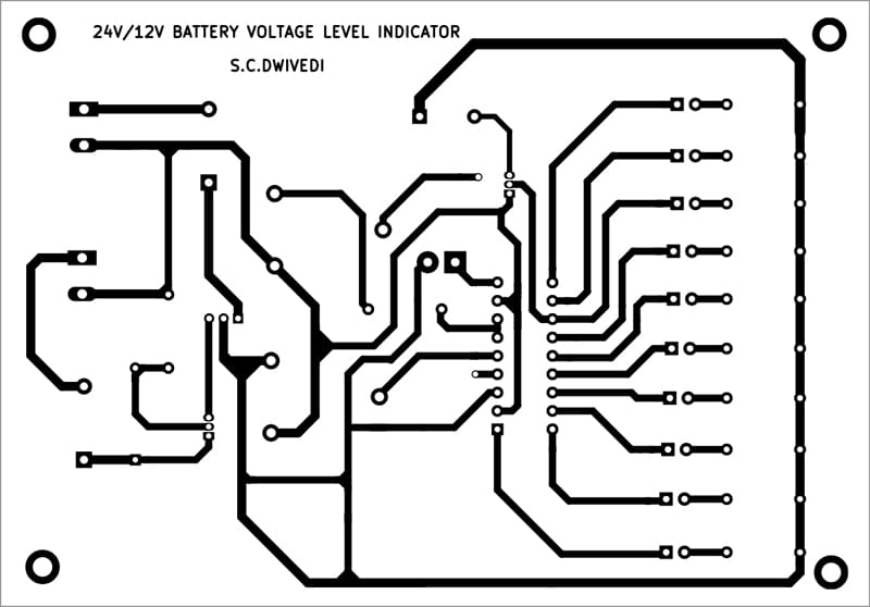
An actual-size, single-side PCB for the 24V/12V battery standing indicator is proven in Fig. 3 and its part format in Fig. 4. After assembling the circuit on PCB, enclose it in an appropriate plastic field. Switches S1 via S2 could also be fastened on again facet of the cupboard. The assembled PCB could also be fastened contained in the field’s entrance facet in such a means that LED1 via LED10 are clearly seen.
BONUS: You may watch the VIDEO of the tutorial for this DIY undertaking click on on the hyperlink.
S.C. Dwivedi is an electronics fanatic and circuit designer at EFY
