Designing wi-fi charging methods for small-size digital gadgets like smartwatches, AirPods, Bluetooth headsets, and so forth. could be very tough. Added to that only some forms of these gadgets help wi-fi charging.
Whereas not one of the earphones at the moment might be charged wirelessly, a charging case is supplied for each charging and storing the earphones. Then again, wi-fi charging know-how is rising with new designs. Few of those designs may even cost gadgets as much as a distance of a meter.You’ll be able to cost whereas it isn’t bodily related to any charger it charging over the air utilizing the electromagnetic waves similar know-how is might be utilized even for these small-sized digital gadgets . Nonetheless, the downside is that only a few(generally none) of those gadgets can really be wirelessly charged. Like earbuds and AirPods should not able to a wi-fi charging system and we can’t use the advantage of this superb over the air really wi-fi charging system so, I’ve determined why not let’s do some experiments and attempt to make a primary circuit that helps us to allow this design a wi-fi charging even in smallest wearable AirPods.
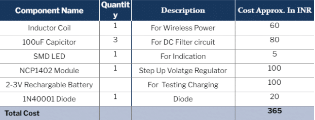
This DIY is a primary circuit that helps us design a wi-fi charging system. A really small coil (inductor with an IC) is used. This circuit can slot in earphones for wi-fi charging and is in a position to slot in wearable watches and different wearable gadgets and small IOT gadgets and assist them to cost wirelessly. The next parts are wanted for this circuit.
Invoice Of Materials
Connection
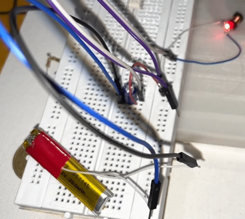
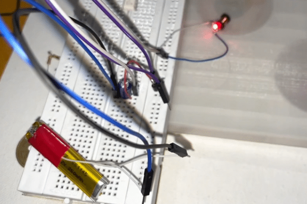
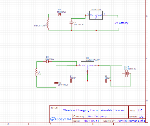
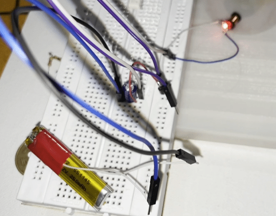
The dimensions of the circuit is saved as small as attainable. Many experiments with wires and coils had been carried out, when immediately the concept of connecting an inductor coil with LED struck. So, technically as per mutual induction concept the coil will induce electrical energy when positioned in an electromagnetic flux and the LED will glow. So this circuit is positioned close to the wi-fi charger and the inductor induced EMF makes the LED glow as proven in determine 2. The inductor is so small (3mm), that it might probably slot in our wearable digital gadgets’ charging circuit. A circuit that filters the present and generates much less noise DC present is added. Subsequent, the voltage needs to be stepped up and controlled to 3V or 5V to energy the machine wirelessly. Therefore the NCP 1402 is added to the circuit.
The parts need to be related as proven within the circuit diagram(determine 3). The primary circuit diagram within the determine is for charging a 1-2V battery that has a voltage regulator of three.3V; and the second is for charging a 3V battery that has a 5V regulator.
Testing
To check the circuit, join the LED( from any good wearable machine) to 1 finish of the circuit and produce it close to the wi-fi charger. The machine is powered on. Subsequent, the battery is related to the output of the circuit and introduced close to the wi-fi charger to ensure that charging to start.

