
This undertaking implements a Good Plug undertaking which may measure the Energy, Present, Voltage of any load linked to it. The Android telephone interface can be utilized to learn the values from the plug and in addition controls its ON/OFF. The values are additionally often despatched to the Android gadget for monitoring.
This undertaking will use an Renesas GR Peach as the primary processor to measure the AC present and voltage of the load utilizing the ACS 712 Present Sensor, a voltage divider and ship the info from a HC-06 Bluetooth gadget to an Android telephone. This circuit additionally has a relay managed by the GR Peach to turn-off and switch -on the load utilizing the Android gadget. The Android telephone runs an App developed on App Inventor and can show the voltage, present, energy and Wh. The App additionally has a graphing characteristic which can show the voltage and present as a bar chart in actual time.
This undertaking will define the strategy to write down and construct the GR Peach program, and in addition writing the Android Software utilizing the cloud software known as App Inventor.
Block Diagram of the system
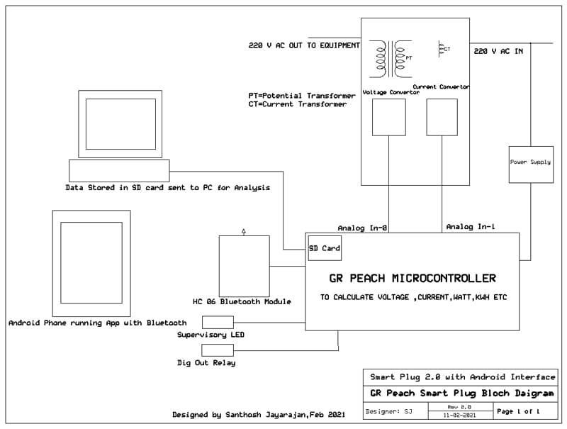
The system consists of the next elements:
- The ACS 712 Sensor (Present Sensor) that may learn the AC Present and generate an analog sign proportional to the AC Present. (1-5000 ma ,185 mv/A AC)
- A 230V to five V rectified circuit (Transformer and rectifier) to learn the AC voltage which is used to calculate energy and Wh. A voltage divider is used to cut back the voltage to the GR Peach vary.
- The GR Peach board which is the guts of the system and reads the voltage and present from the sphere and converts it into energy and Wh(Watt Hour) and ship it serially utilizing the Bluetooth module HC -06.
The GR Peach is a really highly effective growth board which has built-in Ethernet and SD Card capabilities. With the brand new GR – IDE it’s as simple to program because the Arduino. - A Relay module which is managed by Bluetooth command from the Android gadget. This relay is used to show the equipment on and off.
- The HC-06 is a Bluetooth trans- receiver that may settle for alerts from the GR Peach and ship knowledge to a paired Bluetooth gadget on this case the smart-phone.
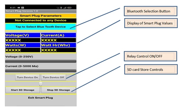
- The Android gadget is a brilliant telephone that runs the App to show the Good Plug parameters present graphing options as effectively.
- The circuit additionally has a supervisory LED to point if this system is working correctly.
This undertaking could be defined as follows:
- The circuit diagram for connection of the ACS 712 Present sensor, Voltage Rectifier Circuit to the GR Peach.
- The Arduino program that reads the Present sensor, voltage alerts convert it to the scaled vary and sends the transformed sign by way of Bluetooth to the Good telephone.
- Growth of the Android App that reads the Bluetooth sign and shows it with bar graphs and labels. (Growth is completed utilizing App Inventor that may be a cloud software to develop sensible telephone Apps.)
GR Peach Good Plug Circuit Diagram

Part Checklist:
-
Sl.No Part Amount 1. Renesas GR Peach Controller Board. 1 2. HC-06 Bluetooth Module 1 3. ACS 712 Present Sensor (0-5 A) 1 4. 0.5 Okay ¼ Watt Resistor 1 5. 5 V Relay – 3.3 Volts Decide-up 1 6. 1N 4001 Diode-Free-Wheeling 1 7. Energy Provide for GR Peach 1
Desk-1 Part Checklist (All elements could be purchased on-line from www.ebay.com, www.amazon.in)
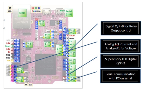
The GR- PEACH Picture is given beneath with the Pin utilization
The GR Peach Good Plug Circuit
The circuit for the GR Peach Good Plug consists of the next Sub Programs:
- The GR Peach is the guts of the circuit and interfaces all the sphere sensors and does the mathematical calculations to calculate energy and Wh.
- A supervisory LED is linked to Pin -2 as a sign that the circuit is working correctly. If the circuit goes right into a non-recoverable infinite loop the LED won’t blink.
- A 5 V relay with a pick-up voltage of three.3 V is linked to Pin 9 to manage the ability to the managed gadget. This relay could be turned on and off through the use of the Android gadget.
- The system voltage is measured through the use of a 230 V/0-5 V transformer with a bridge rectifier and voltage divided to get 3.3 V for 250 V. The calculation of the voltage is completed by the GR Peach. The Analog Enter A1 is used for this enter.
- The system present is measured by an ACS 712 AC Present sensor which can output a voltage proportional to the present utilizing the Corridor Impact. The microcontroller will do a 1 second sampling and discover the utmost and minimal voltage and calculate the RMS present. This Analog enter is linked to A0.
- Bluetooth performance is achieved by a HC-06 Bluetooth Trans-receiver which requires a 5 V provide however has sign degree of three.3 V and thus could be linked immediately with the GR Peach at Serial0 with TX on Pin 1 and RX on Pin 0.
Word: Because the GR peach is basically a 3.3 V gadget all sign together with Analog Enter must be at this degree. For that reason, there are voltage dividers supplied for the voltage and present alerts.
The GR Peach Program in GR-IDE
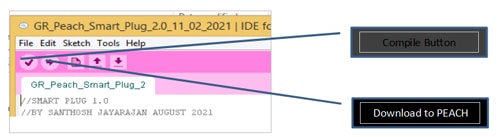
The GR Peach program is given beneath. The GR Peach program could be entered utilizing the GR -IDE and compiled earlier than transmitting to the board utilizing a USB cable.
The assorted variations of the GR -IDE could be downloaded from this hyperlink
After coming into this system and compiling the compiled program could be downloaded into the GR -PEACH.
After downloading the ZIP file from the hyperlink above the file could be unzipped and this system could be run by double clicking on the ide4gr.exe file in the primary folder.
The controls for the compile and obtain are proven within the determine beneath:
The GR Peach program developed utilizing GR IDE
//SMART PLUG 2.0
//BY SANTHOSH JAYARAJAN FEBRUARY 2021
//USED:
//1. 712 SENSOR FOR CURRENT MEASUREMENT
//2. HC-06 MODULE FOR BLUETOOTH COMMUNICATION
//3. 5 V TRANSFORMER FOR VOLTAGE MEASUREMENT
//4. GR PEACH AS THE PROCESSOR
// NOTES:COMPILED – OKAY
///
//
#embody<Arduino.h>
#embody <SD.h>
const int Present = A0;
const int Voltage = A1;
const int RELAY1 = 9;
const int SUPLED = 3;
//START TIMER FOR CURRENT CALCULATION
Timer volt_timer;
File file;
//START A TICK TIMER FOR LED BLINK, BT Ship, WH Counter
Ticker LEDTimer;
Ticker BTTimer;
Ticker WHCount;
//VARIABLE DEFINITION
lengthy CurrRaw;
lengthy CurrCalc;
int c_begin;
int c_end;
int Curr_Max;
int Curr_Min;
int VoltRaw[100];
lengthy VoltScratch_1;
lengthy VoltCalcRaw;
float VoltCalc;
float Volt_m_factor;
float Volt_zero_factor;
//FOR WH COUNTER
float Wh;
//VARAIABLES FOR VOLTAGE CALCULATIONS
float Energy;
int BTin;
//SETUP SUBROUTINE
void setup()
{
//FOR SERIAL0 The Pins used are TX=1,RX=0
Serial0.start(9600);
Serial.start(9600);
}
//SUBROUTINE DEFINITION FOR ENERGY
void WHCounter()
{
Wh=Wh+Energy/360;
}
//READ THE ANALOG CHANNELS
void ReadAnalog()
{
//CALCULATE THE VOLTAGE
Volt_m_factor=1.0;
Volt_zero_factor=0.0;
VoltScratch_1=0;
for(int n=0;n<=10;n++)
{
VoltRaw[n]=analogRead(Voltage);
wait_ms(100);
VoltScratch_1=VoltScratch_1+VoltRaw[n];
}
VoltCalcRaw=VoltScratch_1/10;
//0-1.0 FOR 0-250 V AC volts
//Y=MX+C
VoltCalc=VoltCalcRaw*Volt_m_factor+Volt_zero_factor;
//CALCULATE CURRENT
Curr_Max=0;
Curr_Min=1000;
c_begin=volt_timer.read_ms();
whereas(volt_timer.read_ms()-c_begin<1000)
{
CurrRaw=analogRead(Present);
if(CurrRaw>Curr_Max)
{
Curr_Max=CurrRaw;
}
if(CurrRaw<Curr_Min)
{
Curr_Min=CurrRaw;
}
CurrCalc=(Curr_Max-Curr_Min)*3.3/676;
}
}
//TURN ON RELAY OUTPUT-1
void Relay_1_on()
{
digitalWrite(RELAY1,1);
}
//TURN OFF RELAY OUTPUT-2
void Relay_1_off()
{
digitalWrite(RELAY1,0);
}
//CALCULATE THE POWER PARAMETERS
void CalculatePower()
{
//CALCULATE POWER
Energy=VoltCalc*CurrCalc;
}
//CHECK FOR BT SERIAL DATA
void CheckBTData()
{
if(Serial0)
{
BTin=Serial0.learn();
if(BTin == 1)
{
Relay_1_on();
}
if(BTin == 2)
{
Relay_1_off();
}
if(BTin == 3)
{
if(!SD.start())
{
Serial.println(“Card failed, or not current.”);
}
if(SD.start())
{
Serial.println(“Card OK Saving Information.”);
File file = SD.open(“pattern.txt”, FILE_WRITE);
if(file)
{
file.print(“Present:”);
file.print(Present);
file.print(“Voltage:”);
file.print(Voltage);
file.print(“Energy:”);
file.print(Energy);
file.println( “”r” );
}
}
}
if(BTin==4)
{
file.shut();
Serial.print(“File Closed..”);
}
}
}
//TOGGLE THE SUPERVISORY LED
void ToggleSupLED()
{
if (digitalRead(SUPLED)==1)
{
digitalWrite(SUPLED,0);
}
else
{
digitalWrite(SUPLED,0);
}
//SUPERVISORY LED-2
if (digitalRead(LED1==1))
{
digitalWrite(LED1,0);
}
else
{
digitalWrite(LED1,1);
}
}
//SEND POWER PARAMETERS TO BT DEVICE
void SendBT()
{
Serial0.print(VoltCalc);
Serial0.print(“,”);
Serial0.print(CurrCalc);
Serial0.print(“,”);
Serial0.print(Energy);
Serial0.print(“,”);
Serial0.print(Wh);
//SEND DATA TO PC FOR DEBUGGING
Serial.print(VoltCalc);
Serial.print(“,”);
Serial.print(CurrCalc);
Serial.print(“,”);
Serial.print(Energy);
Serial.print(“,”);
Serial.print(Wh);
}
//MAIN SUBROUTINE
void loop() {
//TIMER TICKER ASSIGNMENT FOR TIME CONTROLLED SUB ROUTINES
LEDTimer.connect(&ToggleSupLED,1.0);
BTTimer.connect(&SendBT,5.0);
WHCount.connect(&WHCounter,10.0);
whereas(1)
{
ReadAnalog();
CheckBTData();
CalculatePower();
}
}
Move Diagram of GR Peach Program
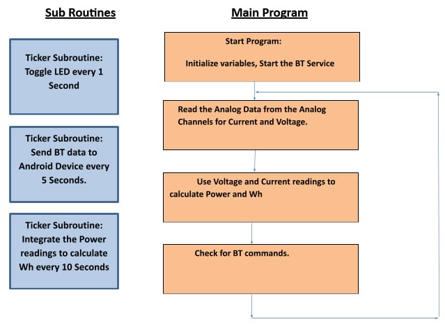
The GR Peach program could be sub divided into two elements:
- The principle Loop Program
- The Timer Ticker program that run at common intervals.
In the primary loop() program we initialize the sub-routine tickers after which repeatedly run the Analog Learn, Energy calculation and test for BT command sub-routines. The Present and voltage are measured by the Analog Inputs and calculation of energy is completed. The principle loop additionally checks repeatedly for any Bluetooth instructions from the Android gadget.
Within the Timer subroutines the assorted time delicate sub routines are run. In the primary loop() subroutine the timer routines are initiated by instructions beneath:
LEDTimer.connect(&ToggleSupLED,1.0);
BTTimer.connect(&SendBT,5.0);
WHCount.connect(&WHCounter,10.0);
The LED Timer is ready to run each 1 second to blink the supervisory LED which signifies the right operation of this system.
The SendBT() sub routine sends the Information of the Good Plug each 5 seconds. The info despatched is voltage, present energy and Wh.
The ultimate sub routine is WHCounter() which runs each 10 seconds to do the mixing of the ability for Wh(WattHour) calculation.
The App Inventor Program
The MIT (Massachusetts Institute of Expertise) staff have produced a Cloud based mostly program that can be utilized to develop apps for Android Telephones or gadgets. This system could be accessed by anybody with a Google account.
The URL for this system is: http://ai2.appinventor.mit.edu/
The appliance makes use of very simple to construct management blocks that may be “latched” collectively to construct this system. This program utilization is similar to Scratch.
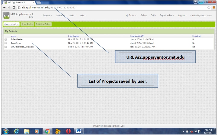
The opening display of this system seems just like the display shot beneath. The opening display opens with the listing of initiatives which were saved.
The required undertaking could be opened by double clicking on the required undertaking.
The programming is completed in two views:
- The Designer view the place the assorted elements are positioned on the palette. This may characterize how the elements look on the gadget.
- The Block view is the place the programming is completed. The assorted programming blocks are interconnected utilizing varied programming features that may snap collectively like a jig-saw puzzle.
To elucidate the fundamentals of working of this system the reason of the assorted sub blocks are as given beneath:
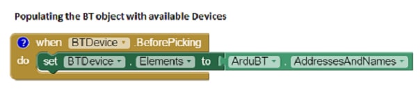
Beginning the Bluetooth System:
Right here the block shows all of the obtainable Bluetooth Units and show the deal with and names. This block is executed earlier than deciding on any Bluetooth gadget. The gadget on this program will seem as HC-06 with a hexadecimal deal with. This a part of this system is required to attach the Android gadget to the HC-06.
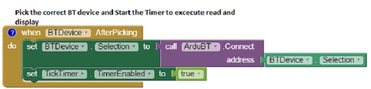
 Deciding on the Bluetooth Units.
Right here the Bluetooth gadget that’s chosen is linked to the cell gadget. This block additionally allows the “Tick Timer” which periodically updates the show and graph.
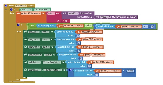
 Principal Timer Block
That is the primary timer block which reads the info from the Bluetooth gadget after which shows the values on the display and in addition attracts the bar graph. After voltage and present values are plotted on a bar chart utilizing the slider management. The updating takes place in actual time. This block checks the info which is shipped by the GR PEACH and separates the info on the commas and masses the values into the assorted textual content containers. The Voltage and the Present are additionally displayed as a bra graph utilizing the slider management.
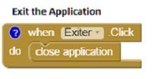
 Exit the appliance
This block is used to give up the appliance.
 Variables used within the software
These are the variables declaration and initialization. On this case the variable is a World variable known as BTReceive.
Within the APP Inventor when the Challenge is Constructed a QR code is generated which could be scanned for speedy set up on the telephone. The APK file may also been generated for storage on the telephone and set up.
![]() A APK model of this system is on the market to immediately load to the Android gadget.
A APK model of this system is on the market to immediately load to the Android gadget.
Conclusion
This undertaking launched a easy approach to make use of the GR Peach board and an inexpensive Bluetooth module the HC-06 to ship knowledge to an Android gadget and show the info and plot the graph.
The essential concept behind this program is to make use of the various capabilities of the Cell gadgets like Colour show, Bluetooth, Wi-Fi and many others. to behave as an interface to gather knowledge from exterior gadgets and manipulate them. On this case the exterior gadget is the GR Peach and the Android System working the Software manipulates and shows the info.
This undertaking additionally launched using App Inventor to write down easy applications for Android gadgets utilizing blocks.
