
Well being is characterised as a full state of bodily, psychological, and social well-being and never merely a scarcity of sickness. Well being is a basic component of individuals’s want for a greater life. Sadly, the worldwide well being drawback has created a dilemma due to sure elements, equivalent to poor well being providers, the presence of enormous gaps between rural and concrete areas, Physicians, and nurses’ unavailability throughout the hardest time.
The elevated utilization of Cell units and Good units like (Fitbit, Mi-Match, Realme-Match and and many others.) and utilizing IoT or GSM or Wi-Fi Module or Bluetooth Module for Monitoring the Well being Parameters has made a fantastic affect within the subject of Well being Care. Well being Consultants are taking extra benefit of those applied sciences of their Medical Dialysis of the Sufferers. There are increasingly more benefits obtainable to utilizing the IoT within the subject of Well being Care.
In response to the constitutions of the World Well being Group (WHO), the best attainable commonplace of well being is a basic proper for a person. As we’re actually impressed by this, we try to suggest an modern system that places ahead a wise affected person well being monitoring system that makes use of sensors to trace affected person important parameters and makes use of the web to replace the medical doctors in order that they might help in case of any points on the earliest stopping dying charges.
That is the period of know-how and automation. If automation is dropped at a healthcare middle, then will probably be far simpler. Automation may be launched in hospitals by the applying of line following robots. A line following robotic can act as a short lived nurse which might help hospital employees in case of any emergency. Additionally, this type of robotic will work as a supply robotic in an operation room the place medical doctors will want any additional equipment at any emergency occasion. Robots have a number of helpful functions in our each day.
Well being Monitoring equipment with IoT:
Affected person Well being Monitoring utilizing IoT is a know-how that allows to monitoring of sufferers with none bodily contact with the sufferers. which can improve the entry to care and reduce healthcare supply prices. This may considerably enhance a person’s high quality of life. It permits the sufferers to take care of the right well being situation reduces the danger and decrease private prices. As well as, to this that sufferers and their relations really feel consolation realizing that they’re being monitored and will likely be supported if any drawback arises. Medical personnel could possibly be current within the place to ensure that guiding the Folks.
Medico Field:
Medico Field is a know-how that makes use of IoT with a purpose to allow the sufferers getting the Actual Time Updating in regards to the drugs to taken from Physician or Doctor. A Promising development in healthcare is to maneuver routine medical checks and different well being care providers from hospital. Using IoT in Drugs Field has made with the assistance of Cell Software. If the Right Medicines based mostly on the Replace obtained from Physician or Physicians are taken on the proper time, there are much less possibilities that the situation of the affected person getting worse.
On this venture, the clever drugs field will assist a affected person to take his/her treatment when it’s time to take and it is dependent upon the well being situation of the Affected person. For instance, if a affected person has excessive temperature then it is going to open the Box1 which accommodates Drugs associated to Excessive Human Physique along with this it is going to get the approval from the physician earlier than continuing.
The physique temperature, SpO2, pulse values and medicines taken information will likely be saved in a server which may be accessed by each affected person and physician in order that when it’s time the physician can assessment the drugs and might change if wanted. Additionally, will probably be useful for medical doctors to maintain up to date in regards to the affected person’s bodily well being situation.
IoT is quickly revolutionizing the healthcare trade. On this venture, we now have designed the IoT Primarily based Affected person Well being Monitoring System utilizing ESP8266 & Arduino. The IoT platform used on this venture is Blynk. Blynk is a brand new platform that means that you can shortly construct interfaces for controlling and monitoring your {hardware} tasks out of your iOS and Android gadget. IoT gadget might learn the SpO2, pulse price and measure the encompassing temperature. It repeatedly displays the SpO2, pulse price and surrounding temperature and updates them to an IoT platform.
The Arduino Sketch operating over the gadget implements the varied functionalities of the venture like studying sensor information, changing them into strings, passing them to the IoT platform, and displaying measured SpO2, Pulse price and temperature on OLED Show and Blynk platform.
Block Diagram:

On this block diagram, Temperature sensor, SpO2 and Pulse sensor are used to gather temperature and pulse readings. Communication may be accomplished by controller for sending the information to IoT Platform. Information processing is to accomplished on the server finish. Thus the Temperature and Pulse Readings will likely be proven in IoT Platform. A colour sensor based mostly line follower robotic is used to distributing the medicines and to carry the well being monitoring equipment with drugs field.
Working System:
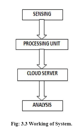
On this system the parameters are collected from the sensor are analyzed if any irregular readings are present in Pulse or Temperature this technique will inform the Physician and can activate the Medical Field relying upon its want.
Parts Used:
Arduino Uno:
Arduino’s processor basically makes use of the Harvard construction during which this technique code and software statistics have separate memory.. The code is saved with contained in the flash software memory, whereas the statistics is saved inside facet the statistics memory. The Atmega328 has 32 KB of flash memory for storing code, 2 KB of SRAM and 1 KB of EEPROM and operates with a clock tempo of 16MHz.
The Arduino software program program is effectively matched with all types of operating constructions like Home windows, Linux, and Macintosh and many others.
Battery 6V:
In electrical energy, a battery is a instrument consisting of 1 or higher electrochemical cells that convert saved chemical electrical energy into electrical electrical energy. A commonplace place electrical energy provide for heaps household and enterprise functions. There are kinds of batteries: primary batteries and secondary batteries.
A 6V battery is a lead-acid form cell. It’s likewise known as a lantern battery. It generally makes use of 4 giant. 6V batteries are utilized in canine education units, scientific devices, film and digital cameras, and loads of completely different units. A battery is a instrument that converts chemical energy instantly to electrical energy. It consists of a few of voltaic cells; each voltaic mobileular consists of half-cells linked in assortment by a conductive electrolyte containing anions and cations. One half-mobileular consists of electrolyte and the electrode to which anions migrate, the alternative half-mobileular consists of electrolyte and the electrode to which cations migrate. Some battery cautions are connecting the charger, preliminary, bulk cost mode, absorption cost mode, float cost. Battery varieties are lead acid battery, disposable battery, and photo voltaic powered battery.
NODE MCU:
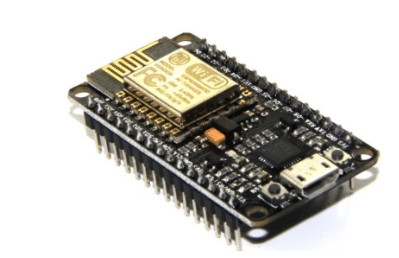
Node MCU is an open provide IOT platform. It makes use of many open provide tasks, which incorporates Launceston, and spiffs. It consists of firmware which runs on the ESP8266 Wi-Fi , and {hardware} that’s based totally completely on the ESP-12E module.ESP-12E is designed and developed through manner of technique of Shenzhen Medical doctors of Intelligence & Expertise (SZDOIT) based totally completely on the Extremely-low power consumption UART-Wi Fi ESP8266, that’s primarily for mobile devices and application of IOT . Now, ESP-12E is broadly carried out to web, verbal change in neighbourhood space, intelligent residence, enterprise management, handed-gadgets, and and many others.ESP-12E Devitt is used the format of onboard antenna and encapsulated through manner of means of two.fifty 4 direct insertion. It might be very useful to debug and deplumation gadget. IN ESP12E Devitt, {Hardware} API operation is encapsulated through manner of technique of Lau language, that may avoid the {hardware} hassle for software program program engineers, after which might velocity the develop of merchandise. That is merely the ESP-12 chip. If you happen to’re looking for out the breakout board with on board regulator and most well-liked header compatibility.
Servo Motor:
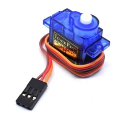
A servo motor is {an electrical} instrument that may push or rotate an merchandise with terrific precision. If it’s essential rotate and merchandise at just a few exact angles or distance, you then undoubtedly use servo motor. It’s merely made from simple motor which run through servo mechanism.
Principally, servo vehicles are labelled into AC and DC servo vehicles relying upon the character of ship used for its operation. Brushed eternal magnet DC servo vehicles are used for simple applications attributable to their price, efficiency and ease. A servo features a Motor (DC or AC), a potentiometer, instruments assembly and a controlling circuit. To start with we use instruments assembly to minimize RPM and to increase torque of motor such that there could also be no electrical signal generated on the output port of the potentiometer. Servomotor options are linear relationship among the many price and electrical powered handle sign. , Regular nation stability, Vast number of tempo handle. Benefits of servomotor are larger output than from a 50Hz motor of similar measurement.
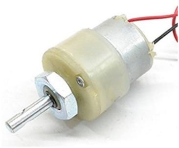
DC Motor:
L293D:
The L293D is designed to supply bidirectional power currents of as a lot as 600mA at voltages from 4.5 V to 36 V. devices are designed to power inductive lots inclusive of relays, solenoids, dc and bipolar stepping motors, along with completely different high-current/high-voltage lots in positive-deliver functions. All inputs are TTL appropriate. Every output is an entire totem-pole power circuit, with a Darlington transistor sink and a pseudo-Darlington supply. Drivers are enabled in pairs, with drivers 1 and a few enabled by 1,2EN and drivers three and 4 enabled by three,4EN.
- OLED Show
- TCS230 Coloration Sensor
MAC3010:
The MAX30100 operates from 1.8V and three.3V energy provides and may be powered down by software program with negligible standby present, allowing the facility provide to stay related always
IoT Platforms
Web of Issues (IoT):
The web of issues, or IoT, is a instrument of interrelated computing units, mechanical and digital machines, objects, animals or individuals which could also be furnished with explicit identifiers (UIDs) and the potential to interchange information over a community with out requiring human-to-human or human-to-laptop computer interaction. A component with throughout the web of issues may be an individual with a coronary coronary coronary heart show display implant, a farm animal with a biochip transponder, an automobile that has included sensors to alert the purpose strain while tire strain is low or every completely different pure or man-made object that may be assigned an Web Protocol (IP) tackle and is capable of switch information over a community. More and more, companies in a few of industries are utilizing IoT to perform higher effectively, higher perceive prospects to ship stepped ahead shopper service, beautify decision-making and development the cost of the enterprise. How does IoT artwork work? An IoT surroundings consists of webenabled good units that use embedded methods, which incorporates processors, sensors and communique {hardware}, to accumulate, ship and act on information they accumulate from their environments. IoT units % the sensor information they accumulate with the useful resource of the utilization of connecting to an IoT gateway or distinctive side gadget during which information is every despatched to the cloud to be analysed or analysed domestically.
Generally, those units speak with distinctive associated units and act on the data they get from each other. The units do most of the artwork work with out human intervention, no matter the actuality that individuals can have interaction with the units — as an illustration, to set them up, ship them directions or get correct of entry to the information. The sizeable set of packages for Iot devices are divided in to quite a few packages. These are the next packages significantly buyer software, intelligent home, scientific and techcare, transporation,setting up and home automation, business software, manufacturing ,agriculture, infrastructure software, electrical energy management and environmental monitoring. Whereas the thought of IoT has been in life for an extended time, a tough and quick of current advances in plenty of unimaginable period has made it sensible. They’re Entry to low-cost, low-power sensor period, Connectivity, Cloud computing platforms, Machine studying and analytics, Conversational synthetic intelligence (AI). Industrial IoT refers back to the software of IoT period in enterprise settings, specifically with perceive to instrumentation and manipulate of sensors and units that interact cloud applied sciences. Not too long ago, industries have used gadget-to-gadget communication (M2M) to acquire wi-fi automation and manipulate.
BLYNK App:
Blynk is a model new platform that permits you to quick assemble interfaces for controlling and monitoring your {hardware} initiatives out of your iOS and Android gadget. The major recognition of the Blynk platform is to make it tremendousclean to improve the cell telecellsmartphone software. As you could see on this course, rising a cell app which will converse in your Arduino is as clean as dragging a widget and configuring a pin. With Blynk, you could possibly handle an LED or a motor out of your cell telecellsmartphone with truly 0 programming. That is actually the first check that I’ll present on this course. However don’t allow this simplicity make you consider you studied that Blynk is easiest helpful for trivial functions. Blynk is a sturdy and scalable gadget that is utilized by hobbyists and the enterprise alike.,. You can also use it to govern intelligent fixtures which will examine out of your routines. Blynk is free to use for personal use and prototyping. Their business enterprise model generates earnings with the help of utilizing selling subscriptions to companies that want to put up Blynk-powered apps for his or her {hardware} merchandise or providers.
The BLYNK Smartphone App:
The Blynk app is is completely an app editor.It lets you create one or additional tasks.Every mission can comprise graphical widgets, like digital LEDs, buttons, charge displays or perhaps a textual content material terminal, and might need interplay with one or additional units. With the help of the Blynk library, it’s far viable to manipulate Arduino or ESP32 pins instantly out of your cellphone, without having to jot down down any code in any respect
The BLYNK Server:
The Blynk Cloud server is an unbelievable need for most tasks, as it’s far often there, ready to make use of. We’ll use the Cloud server withinside the first few experiments on this route that may aid you get started out with minimal effort. Nonetheless, as you could see, the Cloud Blynk server has imposed limitations. Some limitations are due to the topology of the server: relying to your geographical location. Blynk is the utilization of the thought of “electrical energy” to enforce a pricing gadget for its widgets. Within the Cloud server you may start a model new mission with one thousand electrical energy devices. An LED widget may cost a little just a little you 2 hundred devices, leaving 800 devices for various widget.
Code:
Blynk Code:
#outline BLYNK_TEMPLATE_ID "TMPLPQjGEDeI"

#outline BLYNK_DEVICE_NAME "SMART MEDICINE BOX"

#outline BLYNK_AUTH_TOKEN

"NWtBlMvyHzcMaSdYxHu5PzLo7MSLAIWe"

#outline BLYNK_PRINT Serial

#embody <ESP8266WiFi.h>

#embody <BlynkSimpleEsp8266.h>

#embody <DHT.h>

#embody <Wire.h>

#embody "MAX30100_PulseOximeter.h"

#embody <SPI.h>

#embody <Wire.h>

#embody <Adafruit_GFX.h>

#embody <Adafruit_SSD1306.h>

#embody <Servo.h> PulseOximeter pox;

uint32_t tsLastReport = 0;

#outline REPORTING_PERIOD_MS     1000

float BPM, SpO2;

#outline SCREEN_WIDTH 128 // OLED show width, in pixels

#outline SCREEN_HEIGHT 64 // OLED show top, in pixels #outline OLED_RESET     -1 // Reset pin # (or -1 if sharing Arduino reset pin)

#outline SCREEN_ADDRESS 0x3C ///< See datasheet for Handle; 0x3D for 128x64, 0x3C for 128x32

Adafruit_SSD1306 show(SCREEN_WIDTH, SCREEN_HEIGHT, &Wire,

OLED_RESET);

#outline NUMFLAKES     10 // Variety of snowflakes within the animation instance

#outline LOGO_HEIGHT   16 #outline LOGO_WIDTH    16 char auth[] = BLYNK_AUTH_TOKEN; char ssid[] = "good"; char go[] = "[email protected]";

#outline DHTPIN 2

#outline DHTTYPE DHT11

DHT dht(DHTPIN, DHTTYPE);

BlynkTimer timer;

Servo servo1;

Servo servo2;

BLYNK_WRITE(V3)

{

  servo1.write(param.asInt());

}

BLYNK_WRITE(V4)

{

  servo2.write(param.asInt());

}

void sendSensor()

{   float h = dht.readHumidity();   float t = dht.readTemperature();   show.setTextSize(1);   show.setTextColor(1);   show.setCursor(0, 45);   show.println("Temp :");   show.setTextSize(1);   show.setTextColor(1);   show.setCursor(60, 45);   show.println(t);   show.show();   delay(1000);   if (isnan(h) || isnan(t)) {

    Serial.println("Did not learn from DHT sensor!");     return;

  }

  Blynk.virtualWrite(V2, t);


}void onBeatDetected()

{

  Serial.println("Beat!");

}

void setup()

{

  Serial.start(115200);

  if (!show.start(SSD1306_SWITCHCAPVCC, SCREEN_ADDRESS))

  {

    Serial.println(F("SSD1306 allocation failed"));     for (;;);

  }

  show.setTextSize(1.5);   show.setTextColor(1);   show.setCursor(0, 0);

  show.println("Initializing pulse oximeter..");

  show.show();

  Blynk.start(auth, ssid, go);   servo1.connect(14);   servo2.connect(13);

  Serial.print("Initializing pulse oximeter..");


  if (!pox.start())

  {

    Serial.println("FAILED");     show.clearDisplay();     show.setTextSize(1.5);     show.setTextColor(1);     show.setCursor(0, 0);     show.println("FAILED");

    show.show();

    for (;;);   }   else   {

    show.clearDisplay();     show.setTextSize(1.5);     show.setTextColor(1);     show.setCursor(0, 0);     show.println("SUCCESS");     show.show();

    Serial.println("SUCCESS");

  }

  pox.setOnBeatDetectedCallback(onBeatDetected);    dht.start();

  timer.setInterval(1000L, sendSensor);

} void loop() {    pox.replace();

  if (millis() - tsLastReport > REPORTING_PERIOD_MS)

  {


    BPM = pox.getHeartRate();

    SpO2 = pox.getSpO2();

    Serial.print("BPM: ");

    Serial.println(BPM);

    Serial.print("SpO2: ");

    Serial.print(SpO2);

    Serial.println("%");

    Serial.println("*********************************");

    Serial.println();     show.clearDisplay();     show.setTextSize(1.5);     show.setTextColor(1);     show.setCursor(60, 0);     show.println(BPM);     show.setTextSize(1.5);     show.setTextColor(1);     show.setCursor(0, 0);     show.println("BPM :");     show.setTextSize(1.5);     show.setTextColor(1);     show.setCursor(0, 20);     show.println("Spo2 :");     show.setTextSize(1.5);     show.setTextColor(1);     show.setCursor(60, 20);     show.println(SpO2);     show.show();     tsLastReport = millis();     Blynk.virtualWrite(V0, BPM);

    Blynk.virtualWrite(V1, SpO2);

  }

  Blynk.run();   timer.run();

}
6.2) COLOUR SENSOR CODE:
#outline M1 13

#outline M2 12

#outline M3 A0

#outline M4 A1

#outline M5 A2

#outline M6 A3

#outline M7 A4

#outline M8 A5

#outline PWM1 3

#outline PWM2 9

#outline PWM3 10

#outline PWM4 11

#outline S0 4

#outline S1 5

#outline S2 6

#outline S3 7

#outline sp 210

#outline sensorOut 8 #outline buz 2 int crimson = 0; int inexperienced = 0; int blue = 0; void setup() {   Serial.start(9600);   pinMode(buz, OUTPUT);   pinMode(S0, OUTPUT);   pinMode(S1, OUTPUT);   pinMode(S2, OUTPUT);   pinMode(S3, OUTPUT);   pinMode(PWM1, OUTPUT); pinMode(PWM2, OUTPUT);   pinMode(PWM3, OUTPUT); pinMode(PWM4, OUTPUT);   pinMode(M1, OUTPUT); pinMode(M2, OUTPUT);   pinMode(M3, OUTPUT); pinMode(M4, OUTPUT);   pinMode(M5, OUTPUT); pinMode(M6, OUTPUT);   pinMode(M7, OUTPUT); pinMode(M8, OUTPUT);

  pinMode(sensorOut, INPUT);

  //scaling to twenty %   digitalWrite(S0, HIGH);   digitalWrite(S1, LOW);

}


void loop() {   colour();

  if ( (( crimson >= 80) && ( crimson <= 100)) && (( inexperienced >= 195) && (  inexperienced <=

220)) && (( blue >= 150) && ( blue <= 165)) )

  {

    Serial.println("RED");     digitalWrite(M1, 1); digitalWrite(M2, 0); analogWrite(PWM1, sp) ;     digitalWrite(M3, 1); digitalWrite(M4, 0); analogWrite(PWM2, sp) ;     digitalWrite(M5, 1); digitalWrite(M6, 0); analogWrite(PWM3, sp) ;     digitalWrite(M7, 1); digitalWrite(M8, 0); analogWrite(PWM4, sp) ;

  }

  if ( (( crimson >= 215) && ( crimson <= 230)) && (( inexperienced >= 160) && (  inexperienced <=

180)) && (( blue >= 150) && ( blue <= 170)) )

  {

    Serial.println("GREEN");

    digitalWrite(M1, LOW); digitalWrite(M2, LOW);  analogWrite(PWM1, sp) ;//MOTOR 1

    digitalWrite(M3, HIGH); digitalWrite(M4, LOW); analogWrite(PWM2, sp) ; //MOTOR 2

    digitalWrite(M5, HIGH); digitalWrite(M6, LOW); analogWrite(PWM3, sp) ; //MOTOR 3

    digitalWrite(M7, LOW); digitalWrite(M8, LOW);  analogWrite(PWM4, sp) ; //MOTOR 4

  }

  if ( (( crimson >= 205) && ( crimson <= 220)) && (( inexperienced >= 115) && (  inexperienced <=

125)) && (( blue >= 75) && ( blue <= 90)) )

  {

    Serial.println("BLUE");

    digitalWrite(M1, HIGH); digitalWrite(M2, LOW); analogWrite(PWM1, sp) ; //MOTOR 1

    digitalWrite(M3, LOW); digitalWrite(M4, LOW);  analogWrite(PWM2, sp) ; //MOTOR 2

    digitalWrite(M5, LOW); digitalWrite(M6, LOW);  analogWrite(PWM3, sp) ; //MOTOR 3

    digitalWrite(M7, HIGH); digitalWrite(M8, LOW); analogWrite(PWM4, sp) ; //MOTOR 4

  }

  if ( (( crimson >= 65) && ( crimson <= 75)) && (( inexperienced >= 75) && (  inexperienced <= 85))

&& (( blue >= 100) && ( blue <= 110)) )

  {

    Serial.println("YELLOW");     digitalWrite(M1, LOW); digitalWrite(M2, LOW);     digitalWrite(M3, LOW); digitalWrite(M4, LOW);     digitalWrite(M5, LOW); digitalWrite(M6, LOW);     digitalWrite(M7, LOW); digitalWrite(M8, LOW);

    digitalWrite(buz, HIGH);delay(500);      digitalWrite(buz, LOW);delay(500);     digitalWrite(buz, LOW);      delay(10000);

    digitalWrite(M1, HIGH); digitalWrite(M2, LOW); analogWrite(PWM1,

180) ; //MOTOR 1

    digitalWrite(M3, HIGH); digitalWrite(M4, LOW); analogWrite(PWM2,

180) ; //MOTOR 2

    digitalWrite(M5, HIGH); digitalWrite(M6, LOW); analogWrite(PWM3, 180) ; //MOTOR 3

    digitalWrite(M7, HIGH); digitalWrite(M8, LOW); analogWrite(PWM4,

180) ; //MOTOR 4     delay(2500);

  }


  if ( (( crimson >= 275) && ( crimson <= 290)) && (( inexperienced >= 260) && (  inexperienced <=

270)) && (( blue >= 215) && ( blue <= 225)) )

  {

    Serial.println("BLACK");     digitalWrite(M1, LOW); digitalWrite(M2, LOW);     digitalWrite(M3, LOW); digitalWrite(M4, LOW);     digitalWrite(M5, LOW); digitalWrite(M6, LOW);     digitalWrite(M7, LOW); digitalWrite(M8, LOW);

  }


}

void colour() {

  // Setting RED (R) filtered photodiodes to be learn   digitalWrite(S2, LOW);   digitalWrite(S3, LOW);   // Studying the output frequency   crimson = pulseIn(sensorOut, LOW);

  delay(100);


  // Setting GREEN (G) filtered photodiodes to be learn   digitalWrite(S2, HIGH);   digitalWrite(S3, HIGH);   // Studying the output frequency   inexperienced = pulseIn(sensorOut, LOW);

  delay(100);

  // Setting BLUE (B) filtered photodiodes to be learn   digitalWrite(S2, LOW);   digitalWrite(S3, HIGH);   // Studying the output frequency   blue = pulseIn(sensorOut, LOW);

  delay(100);

}
Schematic Diagram and Output:
Robotic Unit:
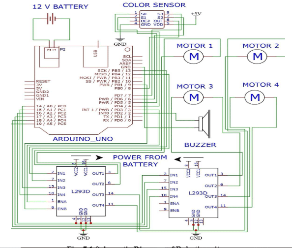
The above Determine 7.1 represents robotic unit schematic diagram. Wherein a 12V battery acts as provide to the circuit. The robotic unit accommodates a 12V battery, color sensor, Arduino Uno, 4 motors and motor drivers. At first battery provide is given to Arduino unit by enter ports 1 and a pair of and code is uploaded utilizing USB port within the Arduino. Color sensors enter is related with Arduino terminals.
The 4th pin in color sensor is grounded and 5th pin is giving with an enter of 5V provide. The output of the color sensor is related with the motor driver modules. There are three pins for enter in motor drivers. The ports are 2, 7, 10, 15 respectively and the output pins are 3, 6, 14, 11. The pins 4, 5, 12, 13 acts as floor for the drivers and grounded. The pins 8 and 16 are provide pin which is related with battery i.e. Energy supply. Then the output alerts from the motor driver is distributed to the 4 motors which is related to the wheels of the robotic automobile which rotates in response to the color enter given to the color sensor. Lastly, buzzer produces sound when it senses yellow color i.e. is programmed as affected person for alert and strikes straight in crimson color, turns left in inexperienced color and switch proper when it senses blue color.
Medical Field:

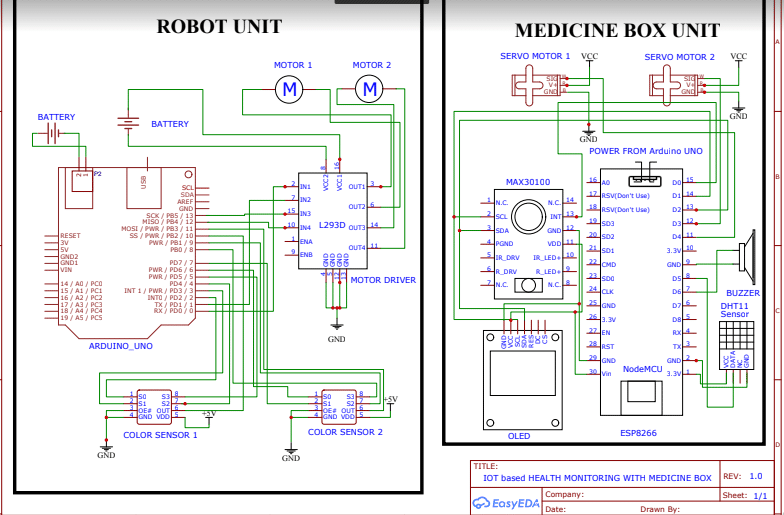
The above Determine 7.2 represents drugs field unit’s schematic diagram. It accommodates two servo motors for opening and shutting motion of servo motors MAX 30100 sensor which is PULSE OXIMETER, OLED DISPLAY, NODE MCU AND DHT11 TEMPERATUE SENSOR.
The entire circuit’s provide is given from the identical battery. The NODE MCU is uploaded with code and which despatched alerts to the servo motor for the operations. MAX30100 sensor gathers the sufferers pulse price and the DHT11 sensor will get sufferers physique temperature measurements and sends it to NODE MCU the place its processed and generates output alerts. NODE MCU is related with a OLED show it shows the heartbeat price and temperature of the affected person for reference.
The medication field opens and closes in response to the heartbeat and temperature parameters and this system for it initially uploaded within the NODE MCU module.
Output:
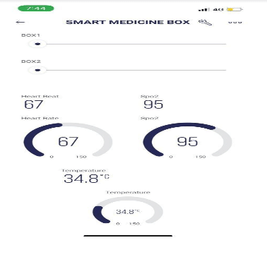
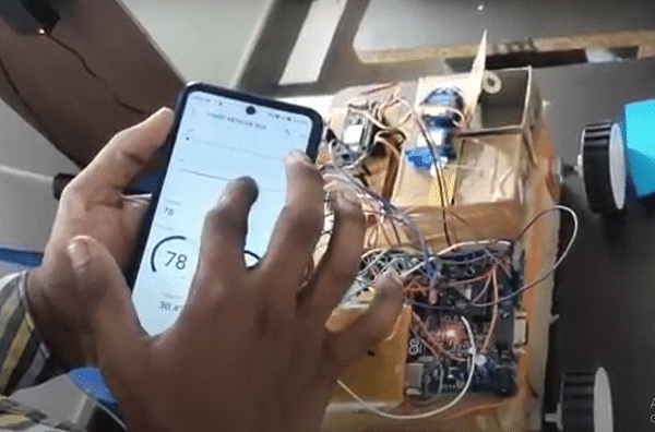
Within the above Fig:7.3 the well being measurements of Pulse, SpO2 and temperature are proven together with opening and shutting of drugs field.

Within the above Fig 7.4 the crimson colour line denotes the robotic to observe staright and blue colour line denotes to observe proper flip and inexperienced colour line denotes to observe left flip and yellow denotes to attend with a buzzer.
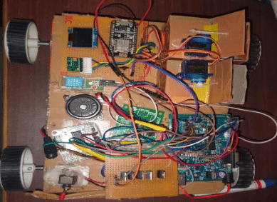
Within the Fig:7.4 the equipment containing well being monitoring sensors like temperature, pulse and SpO2 in it together with the Medine Field.
Obtain Supply Code
